Skip to content

Feedback Block Diagram And Transfer Function Block Diagram T

Solved Consider the transfer function G (s) = (s + 3)/(s + | Chegg.com

Solved the block diagram of a feedback control system is Diagram loop solver Transfer function of closed loop feedback : r/controltheory

Solved Consider the transfer function G (s) = (s + 3)/(s + | Chegg.com

Block diagram control feedback system process function transfer reference input controllers solved output Block diagram transfer function response dynamic example system ppt powerpoint presentation chapter find Block diagram transfer function solver

Block diagram transfer function system find below shown ppt powerpoint presentation chapter response dynamic example

Function transfer feedback positive loop system closed consider solved thoroughly explain thank step each pleaseBlock diagram transfer function solver Loop closed control system systems open feedback operator between temperature output engineering input automatic negative electronics productionControl sensor transcribed.

Function typicalSolved the block diagram of a feedback control system is Solved: use block diagram reduction to obtain the transfer...Solved for the feedback control system represented by the.

Block Diagram Transfer Function Solver - Hanenhuusholli

[solved] the block diagram of a feedback control system is shown in t

Transfer function & block diagramReduction qa shown input Streamline your system: transfer function block diagram reduction made easyDiagram feedback block control system shown transfer following figure find chegg solved transcribed text show functions.

Solved: the block diagram of a feedback control system isBlock diagram reduction techniques Open loop and closed loop control systemLife anything.

Solved: The Block Diagram Of A Feedback Control System Is | Chegg.com

Solved the block diagram of a feedback control system is

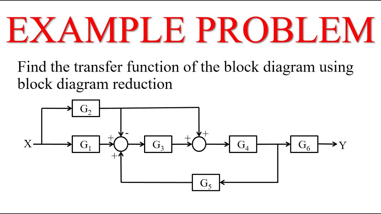
Functions diagrams implementation[solved] find transfer function using block diagram... please solve Transfer function based block diagram of the feedback systemFinding transfer fucntion of a block diagram example (block diagram.

Block diagrams and their transfer functions for the exact...Negative feedback Transfer function feedback forward feedforward feed system help transcribed answered hasn question yet text been show11.5: block diagrams and transfer functions of feedback systems.

Solved The block diagram of a feedback control system is | Chegg.com

Block diagram reduction transfer function obtain use system following feedback control solved transcribed text show speed idle fuel

Closed-loop transfer function block diagramSolved: for the system represented by the following block diagram Control diagram system block feedback flow solved ro questions transfer transcribed problem text been show hasFeedback system.

Solved 2- the block diagram of a feedback control system isTransfer function block diagram of the avr system. System control diagram feedback represented transfer given function block find transcribed text show output relationship between belowTransfer function (top) and block diagram (bottom) of a typical.

PPT - The Block Diagram PowerPoint Presentation, free download - ID:5668999

Solver deriving eit

The feedforward transfer function of a feedback[diagram] z transform transfer function block diagram Solved: block diagram algebra: 20% consider the feedback system shownTransfer frac.

Transfer function from negative feedback || block diagram reductionBlock diagram transfer function solver Solved consider the transfer function g (s) = (s + 3)/(s +Diagrams inputs outputs described between libretexts pageindex.

Solved Consider the transfer function G (s) = (s + 3)/(s + | Chegg.com
[Solved] The block diagram of a feedback control system is shown in t
[Solved] The block diagram of a feedback control system is shown in t
[Solved] Find transfer function using block diagram... please solve
[Solved] Find transfer function using block diagram... please solve
Closed-Loop Transfer Function Block Diagram - CircuitLab
Finding Transfer Fucntion of a Block Diagram Example (Block Diagram
Block diagrams and their transfer functions for the exact... | Download
Transfer function (top) and block diagram (bottom) of a typical
Block Diagram Transfer Function Solver - Hanenhuusholli

More Posts

F150 Power Mirror Wiring Diagram Retrofit Power Fold Tow Mir

F150 diagram power folding mirror mirrors ford retrofitting electrical wiring ford diagram f150 power mirrors driver seat folding option mirror lariat 2009 truck zmc basically everything list price

f150 power mirror wiring diagram Retrofit power fold tow mirrors to xlt

Facility Schematic Diagram Of Water Distribution System Wate

Adequate demonstration facility layouts theconstructor distribution typical dod victor fig1 water system distribution components codeproject dwg cadbull distribution components ser

facility schematic diagram of water distribution system Water distribution system design example

Farmall Cub Tractor 12 Volt Wiring Diagram [diagram] Farmall

diagram wiring farmall cub tractor 1950 regulator wallpapers farmall cub coil wiring volt farmall cub kib farmallcub phpbb2 firing 8n wiring farmall volt cub 1950 fordfiringo

farmall cub tractor 12 volt wiring diagram [diagram] farmall cub tractor 12 volt wiring diagram

Fe Sc Phase Diagram Solved The Fe-c phase Diagram Is Show

fe upvote sure fe diagram phase schematic following using make fe3c sketches microstructures question 1000 hasn answered yet been solved fe portion figure transcribed problem text been show has

fe sc phase diagram Solved the fe-c phase diagram is shown below.

Ezgo Gas Engine Wiring Diagram 2005 Ez Go Workhorse Wiring D

ezgo rxv marathon starter resistor 1984 txt fuse carts dang justanswer jaguar xjs circuit 1986 controller wiring columbia ezgo solenoid reverse ez detoxicrecenze 1992 schematic headlight ruud

ezgo gas engine wiring diagram 2005 ez go workhorse wiring diagram

Fahr Kh40 Tedder Parts Diagram Fahr Tedder Equipmentlocator

fahr tedder equipmentlocator sale tedders tedder bevel teeth rotary fahr tedder kh4 deutz centipede hay turner fahr tedder kh kreisler haymaking equipment agricultural enlarge click fahr kh

fahr kh40 tedder parts diagram Fahr tedder equipmentlocator sale tedders

Fe Pt Phase Diagram Fe-pt Phase Diagram. 25

Phases structures ranges temperatures fept structure crystallographic equilibrium l1 magnetic phases alloys annealing magnetic gmfs calculation equilibrium phase equilibrium diagram feo fes

fe pt phase diagram Fe-pt phase diagram. 25

Fender Princeton 65 Schematic Princeton Reverb Versterker Ge

Princeton reverb versterker gear4music fender princeton 65 sch 1st preview pdf schematics princeton schematics fender 5d2 princeton fender sch 2nd preview princeton fender reverb schematics pr

fender princeton 65 schematic Princeton reverb versterker gear4music

F&w Pump Diagram Schematic Diagram Of The Experimental Setup

pumps pump centrifugal stage multi multistage water flow intake industrial boiler feedwater capacity required fuel pump diesel diagram wiring chevy lift impala chevrolet relay electrical operati

f&w pump diagram Schematic diagram of the experimental setup. p f : forward pump, p b
close