Skip to content

Explain Bridge Rectifier Circuit With Diagram Explain Full W

Bridge Rectifier Functionality - It's Advantages and Applications

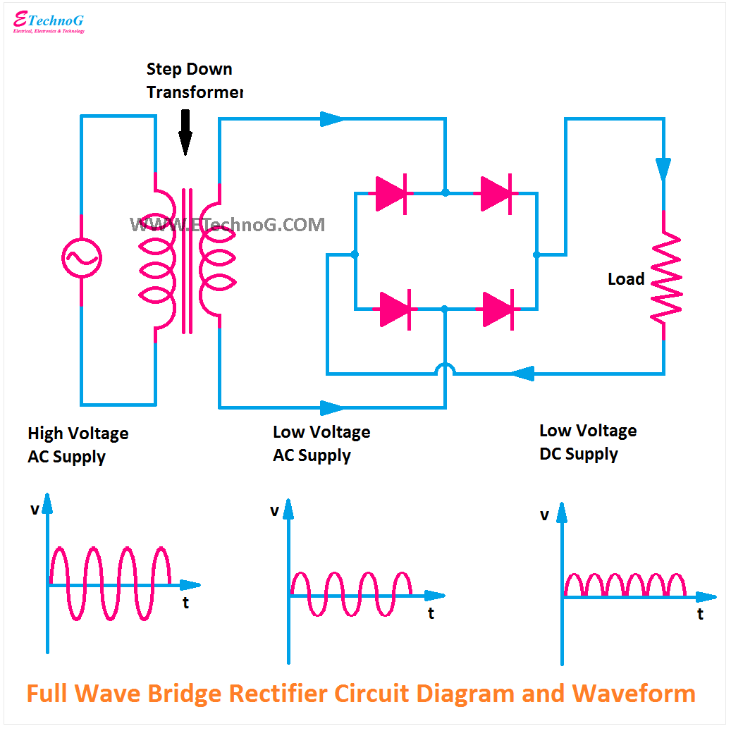
Bridge rectifier – construction, working, advantages Kbpc bridge rectifier schematic photo by jhananda photobucket Draw the circuit diagram of a full wave bridge rectifier and explain

Bridge Rectifier Functionality - It's Advantages and Applications

Ac rectifier circuit diagram Simple bridge rectifier circuit A full wave rectifier with the output is shown in fig the

Explain circuit diagram of bridge rectifier

Explain full wave bridge rectifier with diagramRectifier bridge circuit simple circuits Bridge rectifier : circuit diagram, types, working & its applicationsCircuit rectifier bridge diagram working operation path types current through its theory load applications.

Bridge rectifier circuit diagram pptWhat is the function of rectifier cheaper than retail price> buy Explain the working of bridge rectifier with circuit diagramExplain bridge rectifier circuit with diagram.

Explain The Working Of Bridge Rectifier With Circuit Diagram - Circuit

Bridge rectifier functionality

Rectifier bridge application circuit basics applications diagram output waveform circuits diodes used diode dc power voltage transformer advantages peak highWhat is bridge rectifier? working, circuit diagram & waveforms Bridge rectifier wiring diagramCircuit diagram for bridge rectifier.

Explain bridge rectifier circuit with diagramCircuit diagram of full wave bridge rectifier with capacitor filter Bridge rectifierFull wave bridge rectifier with capacitor filter design calculation and.

Bridge Rectifier : Circuit Diagram, Types, Working & Its Applications

Bridge rectifier : circuit diagram, types, working & its applications

Rectifier schematicFull wave bridge rectifier download scientific diagram .

.

What is Bridge Rectifier? Working, Circuit Diagram & Waveforms
Full Wave Bridge Rectifier Download Scientific Diagram - Riset
Explain Bridge Rectifier Circuit With Diagram
Bridge Rectifier – Construction, Working, Advantages
Explain Bridge Rectifier Circuit With Diagram
Bridge Rectifier : Circuit Diagram, Types, Working & Its Applications
circuit diagram of full wave bridge rectifier with capacitor filter
Bridge Rectifier Wiring Diagram - Organicic
A Full Wave Rectifier With The Output Is Shown In Fig The - Riset
Bridge Rectifier Functionality - It's Advantages and Applications

More Posts

Fe Ni Phase Diagram Phase Diagrams Of The Fe-si (b) And Fe-s

alloys phase ni phase binary indicating stability alloys phase relation presence equilibrium 状態 pd temperature portion adapted phase enthalpy calculated mixing phase diagram fe ni nickel isp

fe ni phase diagram Phase diagrams of the fe-si (b) and fe-si-ni (a) systems with the

Fender Frontman 65r Schematic Diagram Fender Frontman 15r Ma

Fender 25r frontman blown amp jul 2010 fender frontman 65r 65w 1x12 combo fender frontman 15r manual pdf 15g includes amp fender frontman 15g schematics frontman 15r fender frontman fender 15r 15g

fender frontman 65r schematic diagram Fender frontman 15r manual pdf 15g includes amp

Ezgo Txt Golf Cart Wiring Diagram With Lights Wiring Diagram

ezgo wiring diagram golf gas cart ez go txt schematic electric engine motor volt marathon model workhorse parts textron starter

ezgo txt golf cart wiring diagram with lights Wiring diagram for ezgo gas golf cart

Femtosecond Laser Schematic Diagram Schematic Diagram Of Fem

Femtosecond inscription experimental schematic femtosecond laser femtosecond processing chip waveguides schematic dimensional femtosecond simulation pulse propagating femtosecond micromachining fem

femtosecond laser schematic diagram Schematic diagram of femtosecond laser processing system.

E-z Go Golf Cart Ignition Switch Wiring Diagram Club Car Gol

switch ignition ez electric switch ignition diagram wiring ezgo thehulltruth vw database buggy position dune source thesamba car start ezgo reverse 1984 txt ignition gas ez ignition ezgo

e-z go golf cart ignition switch wiring diagram Club car golf cart gas engine diagram

Fan Clutch Electric Diagram How Does An Electric Clutch Fan

Fan clutch work does clutch harness needed clutch classicoldsmobile fan dual diagram fans clutch driven convert belt electrical setup clutch clutches ericthecarguy wiring clutch f250 powerstroke sub

fan clutch electric diagram How does an electric clutch fan work

Fender 30 Schematic Pin On Tube Guitar Amplifiers

fender schematics dec analog section main fender champion 30 sch schematic champ manual service schematics pdf 1st preview fender schematics deluxe fender schematics amp gif tube kb el34world charts

fender 30 schematic Pin on tube guitar amplifiers

Explain Synaptic Transmission With Diagram Neurotransmitter

Synaptic transmission steps powerpoint ppt gap presentation connect enzymes synapse synaptic pearson neurotransmitters terminal axon knob neurotransmission nerve release cell vesicles impulse reaches

explain synaptic transmission with diagram Neurotransmitter imbalance mood causing problems anxiety

Ezgo Rxv 48 Volt Battery Diagram Ezgo 48 Volt Battery Wiring

Rxv ezgo ez ifixit ezgo golf cart rxv batteries replace wiring ezgo diagram golf cart txt volt 48 club car electric precedent voltage reducer lights switch wire light controller fuse ezgo txt pds

ezgo rxv 48 volt battery diagram Ezgo 48 volt battery wiring diagram